Radiation Monitoring Computer System (RMCS) Screen Shots
Apr 24, 2024
Click on any of the screen shots below to see a full size, full resolution version of the screen. Please note that the data being used to generate these screens comes from a pseudorandom number generator, NOT real, live hardware. Most of these screens' layout is defined by plain text configuration files that may be changed, added and/or deleted while the display program is running (just reload the page to see the effect of changes).
Display Screen Features
- RMCS Display may be run full screen, without a caption or menu with the menu optionally dropping down into visibility when the mouse approaches the top of the screen. The screen shots captured here show the program running in a maximized window instead.
- The outer border of the display area is filled with either green or red to indicate the current setting for Audio Enable. This allows anyone to see that audio alarms are disabled from across the room.
- The font used for the display is selectable and RMCS Display may be configured to stretch the font so that the display area is maximized.
- Tooltips are used over channel tags on grids and over RM-80 tags on other screens to show current values, status, and sometimes English translations of internal codes used by the software (typically done when space limitations did not allow the translated values to be displayed directly).
- Context menus are available for channel tags on grids, for RM-80 tags and for Loops. These menus provide information (like the description) and quick access to screens relating to the object whose context menu is being displayed.
Master Menu
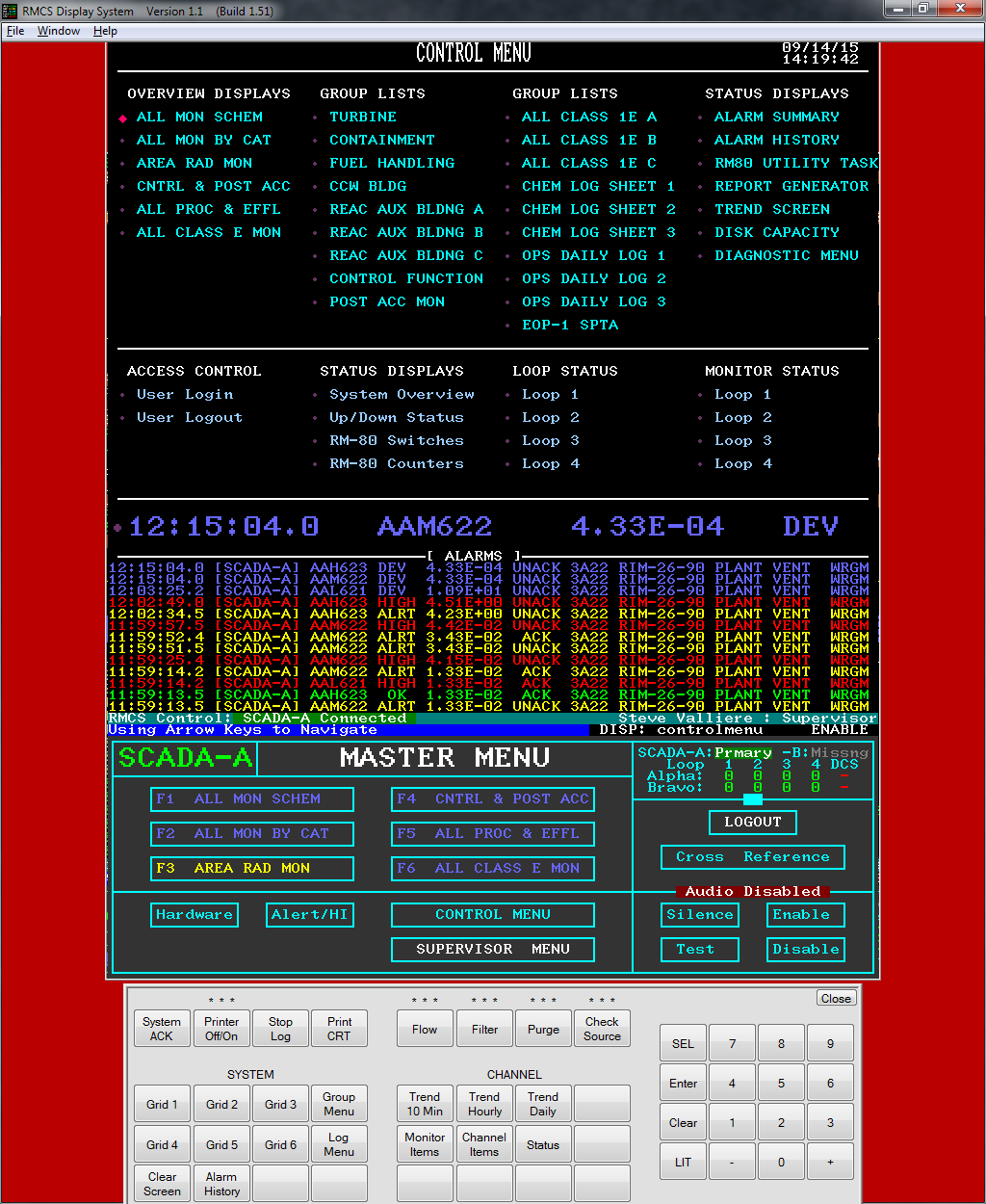
Almost every screen in RMCS Display has a MASTER MENU attached, either at the bottom (as shown here) or at the left (as shown in later images). The master menu provides quick, direct access to many of the most commonly accessed screens and functions. Some of the buttons on the menu are only visible when a minimum security level is met, for example, Guests cannot see the Acknowledge All or Logout buttons (among others).
In addition to buttons, the master menu also shows a small loop summary block and the name of the RMCS subsystem, whose color shows the subsystem's role: green for primary, orange for backup and blue for standalone (aka peer). The grid buttons may be colored by the worst alarm on the grid, which makes finding an alarm quick and easy.
To make screen design and maintenance easier, the menu is stored in a separate layout file that is automatically loaded by all other screens that include it.Overview Screens
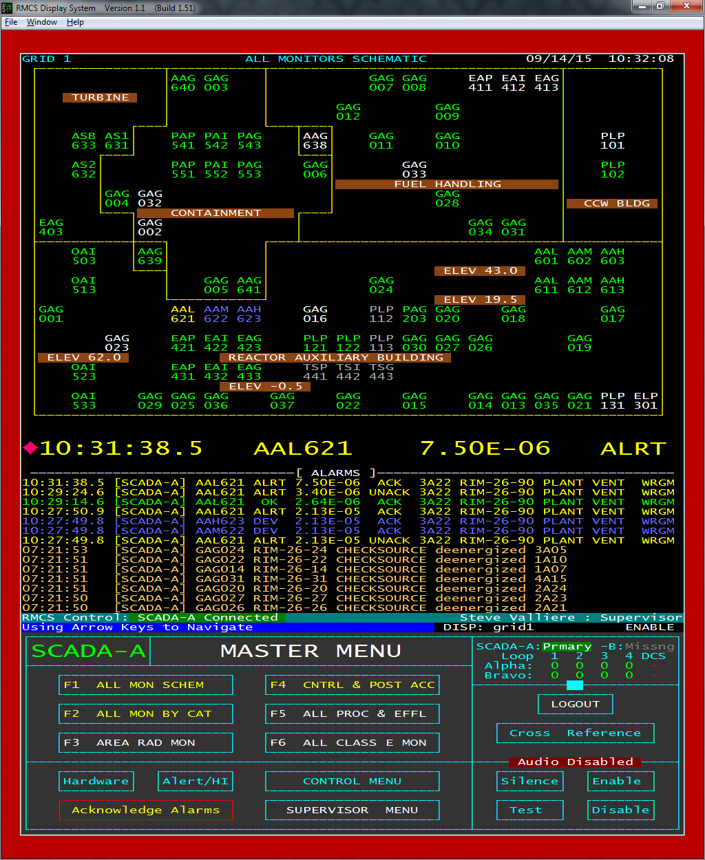
"GRID" screen, showing stylized layout of radiation detectors using the detector channel names formatted into a 3x2 text block that uses color to indicate current condition (e.g. green is normal, yellow is ALERT alarm, etc.) A supervisor-level user account is currently logged in to the system, enabling all RMCS functions.
Channel items on a grid will display a tool tip showing the current channel status, value and an attempt to explain why an off-normal condition exists.
Clicking on a channel item will switch to the associated RM-80's MASTER Flow screen (even if the RM-80 has no flows). Right-clicking on channel items activates a pop-up menu that allows you to go directly to any MASTER screen (described below) as well as some of the diagnostic status screens for the RM-80.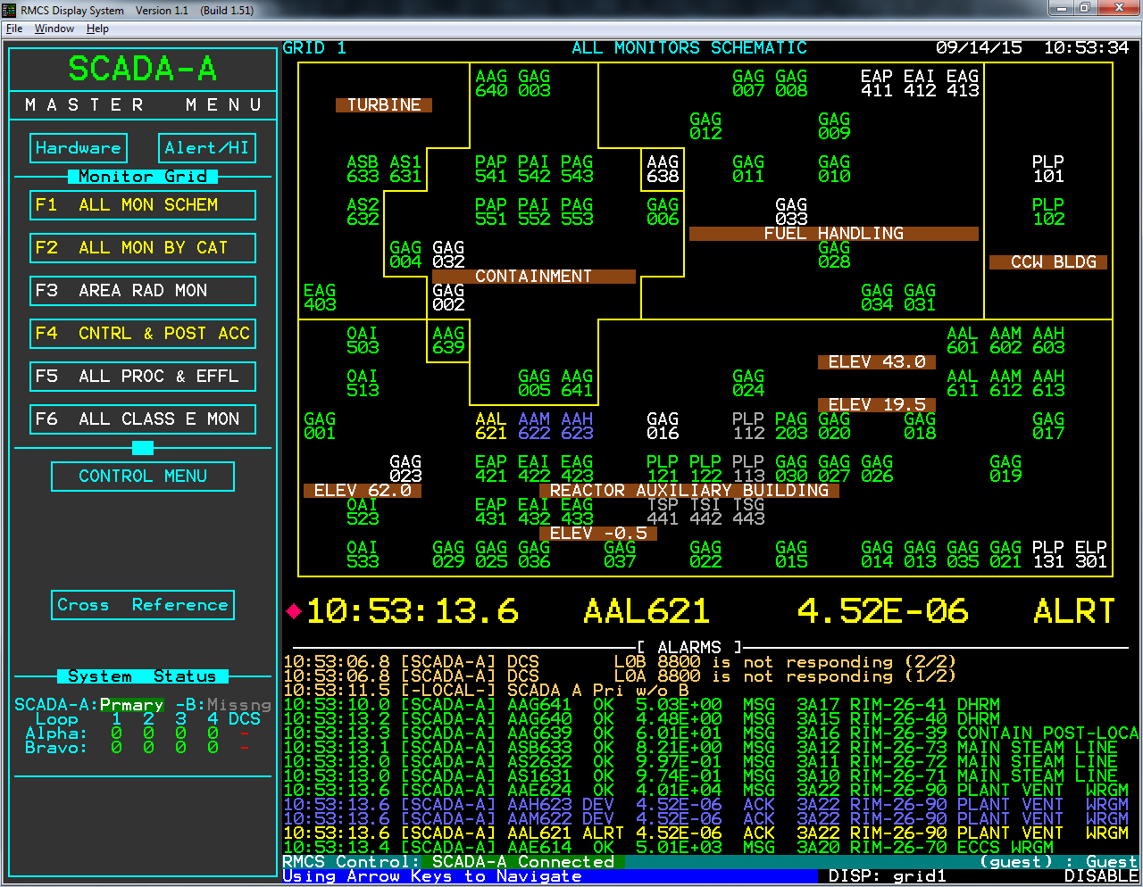
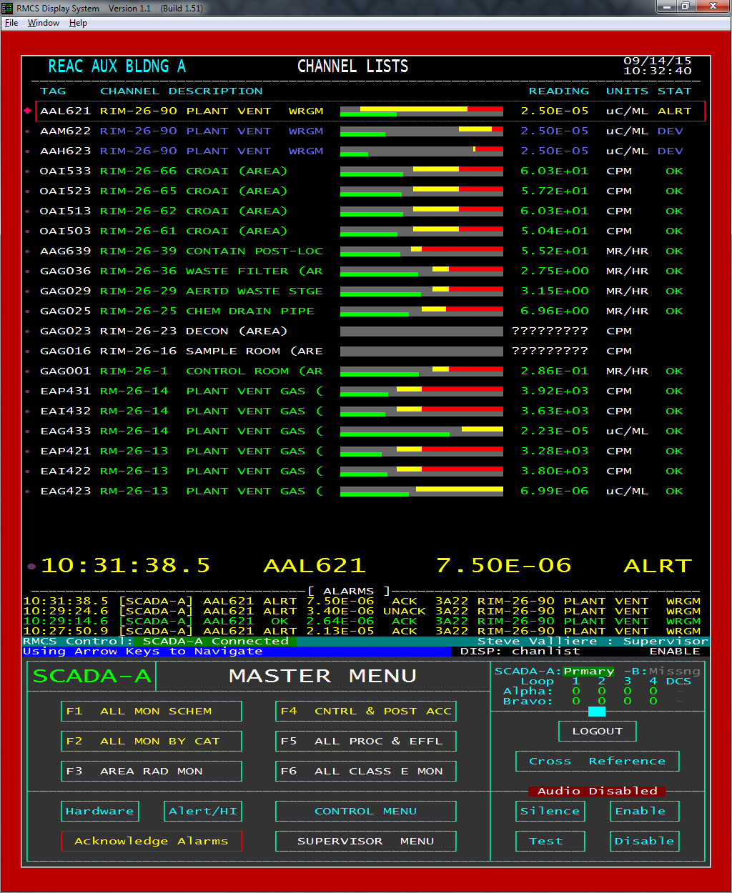
RMCS allows customers to define groups of points for use on CHANNEL LIST report screens. These screens show the current status and value of many points at the same time. The bar graphs provide a visual clue about how close a channel's value may be to an alarm limit.
Clicking a channel item activates the channel's CHECKSOURCE / FILTER ADVANCE control dialog (which also provides direct access to the various MASTER sub-pages, see below).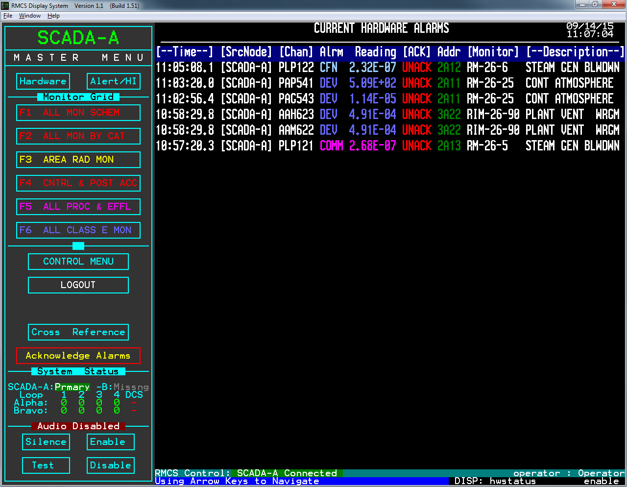
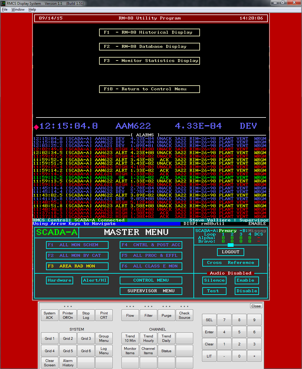
The Hardware button on the MASTER MENU activates a screen that shows all of the CURRENT HARDWARE ALARMS. Both acknowledged and unacknowledged hardware alarms are listed on this page. The alarms are sorted by date/time with the NEWEST at the TOP of the screen. This is a dynamic display, if an acknowldged alarm clears, it will be immediately removed from the screen.
(The double-height characters for the alarms is optional. Using single-height text would allow twice as many alarms to be visible.)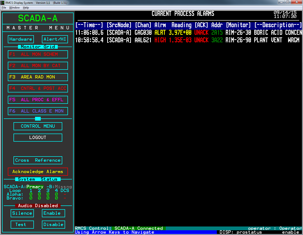
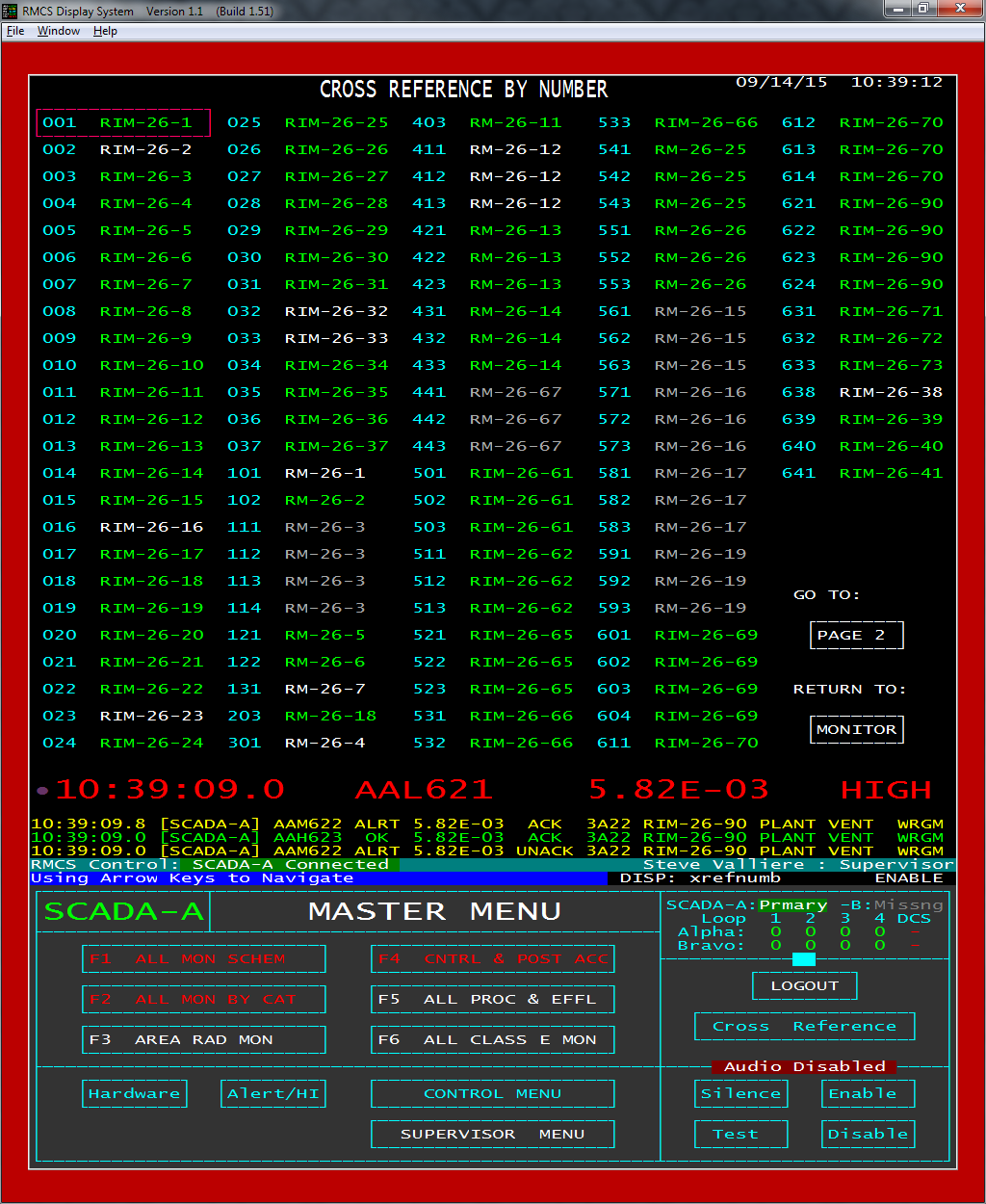
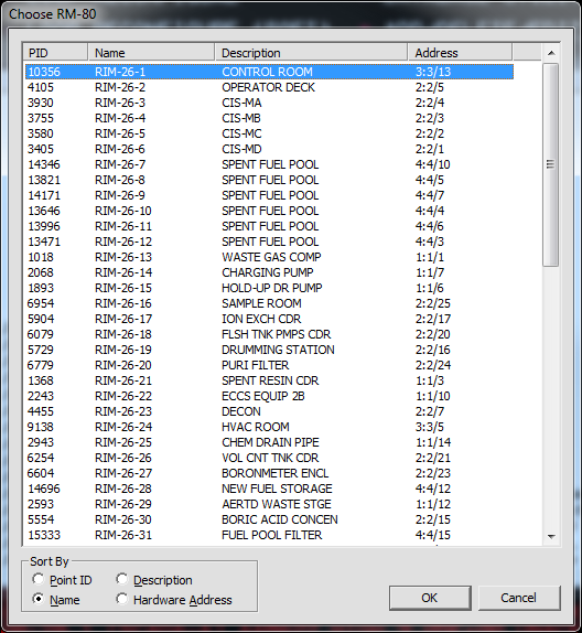
To help locate specific RM-80s by channel ID number or RM-80 name, RMCS Display includes a pair of cross reference screens. These screens color the RM-80 names by condition (normal, out of communication, configuring, offline or alarms disabled) and may provide a quick overview of the current status of all RM-80s at once. Clicking on an entry activates the MASTER screen for the selected item.
Note that this RM-80 coloring is used on almost all screens where RM-80 names are displayed.Menu Screens
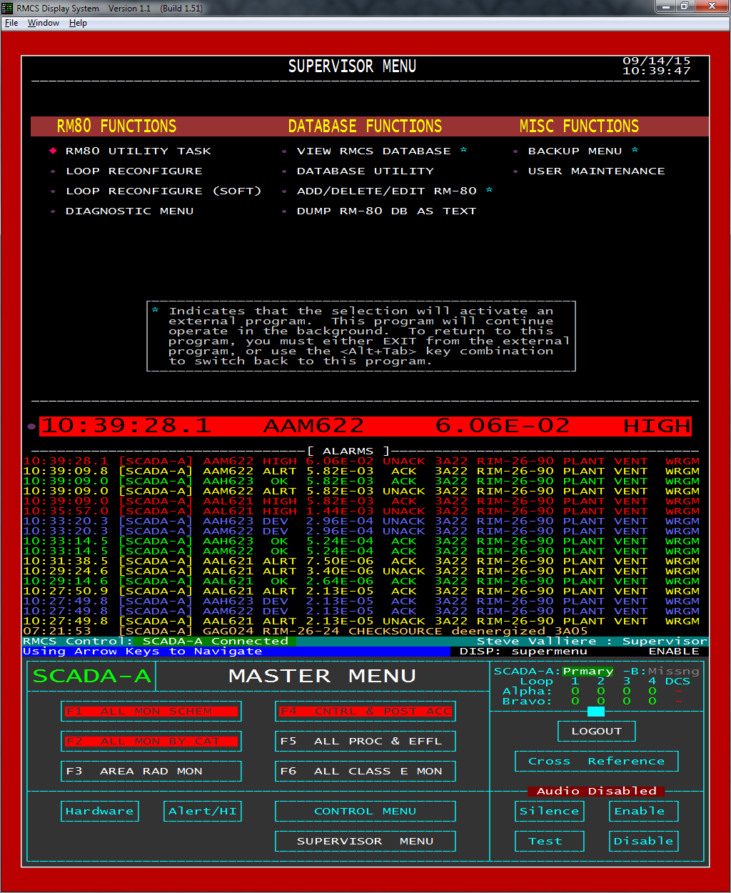
Supervisor Tools
LOOP RECONFIGURE allows a supervisor to force RMCS to send a loop through a configuration cycle. This will cause data collection to be stopped on the loop side being configured for 20 to 40 seconds. The other side will still collect data if it is active.
The (SOFT) version of this screen will force a soft configuration to be triggered. Soft Reconfigure does not disrupt polling the RM-80s as normal reconfiguration does. Instead it adds to the polling cycle the normal configuration message which causes RM-80s blocking downstream communication to open it back up. As with normal configuration, it ends when no RM-80 responses to the message.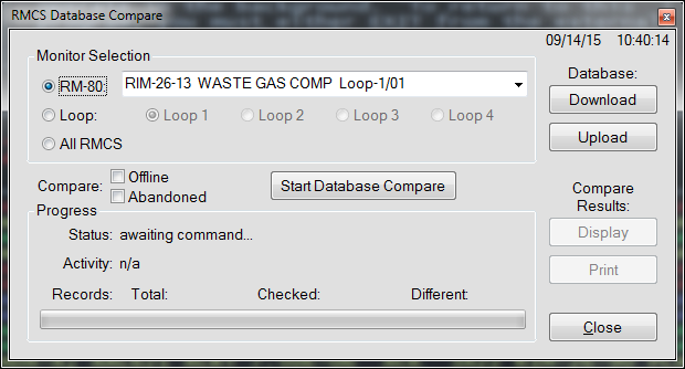
The Database Utility can compare the CURRENT and MASTER database for a single RM-80, an entire LOOP or the entire RMCS. The Upload & Download buttons will force an upload or download on an RM-80 or Loop.
When a comparison finds differences, the Display and Print buttons are enabled. Within the Display window, it is possible to force database items to match by sending an update either to the MASTER database or to the RM-80, by individual item, groups of items or all items.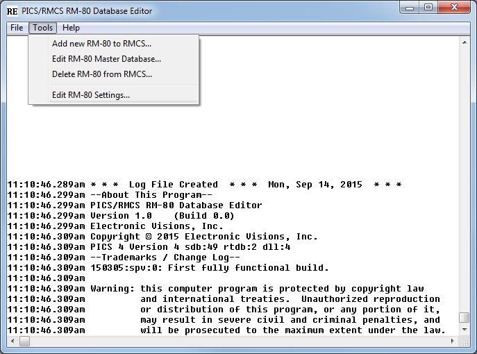
While it seems to be rare, sites occasionally may add, remove or replace an RM-80. The RM-80 Editor makes the process of adding the necessary records to the RMCS database (or removing them) as easy as possible. A new RM-80 may be defined from scratch or "cloned" from a similar, existing RM-80.
Any RM-80's MASTER database may be directly edited using this tool. This is easier, safer, and more efficient than booting an RM-80 with whatever is in the MASTER database, updating the RM-80's CURRENT database as needed and then committing the changes to the MASTER database.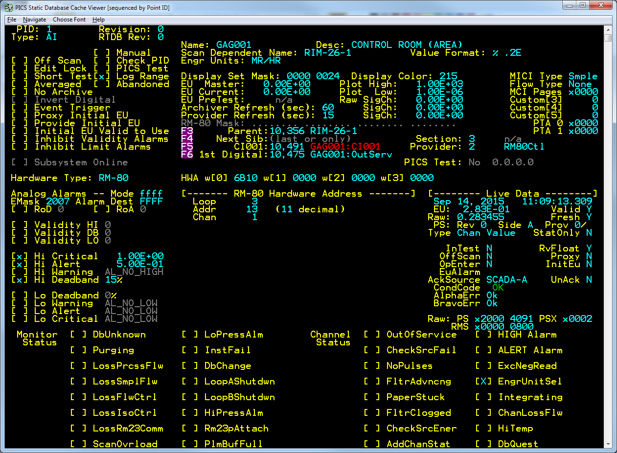
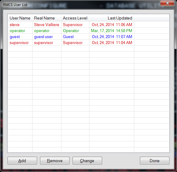
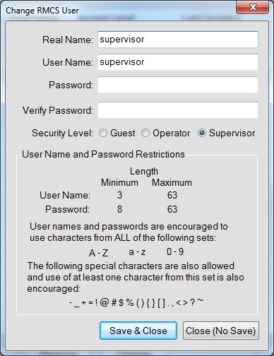
Currently, the RMCS Display program is the agent for RMCS user access control. All RMCS programs that are capable of making changes to the system get the currently user's access level from RMCS Display (and use GUEST unless RMCS Display tells them otherwise).
The RMCS User Editor is built-in to RMCS Display and begins by showing a list of all currently defined user accounts.RM-80 and CHANNEL Screens
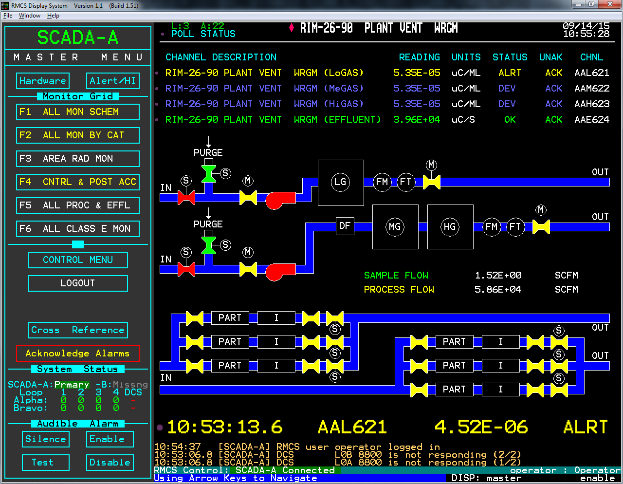
Any time that a channel reading is clicked or entered into the user input area, the RM-80 MASTER screen is displayed. The top portion of this screen contains the RM-80 tag, description and address along with a row for each channel on the RM-80. The next part of the screen may contain several different types of information, all relating to the selected RM-80.
This example screen shows the flow diagram for a WRGM. The flow diagram screen is the standard entry screen, even for area monitors whose flow diagram is blank.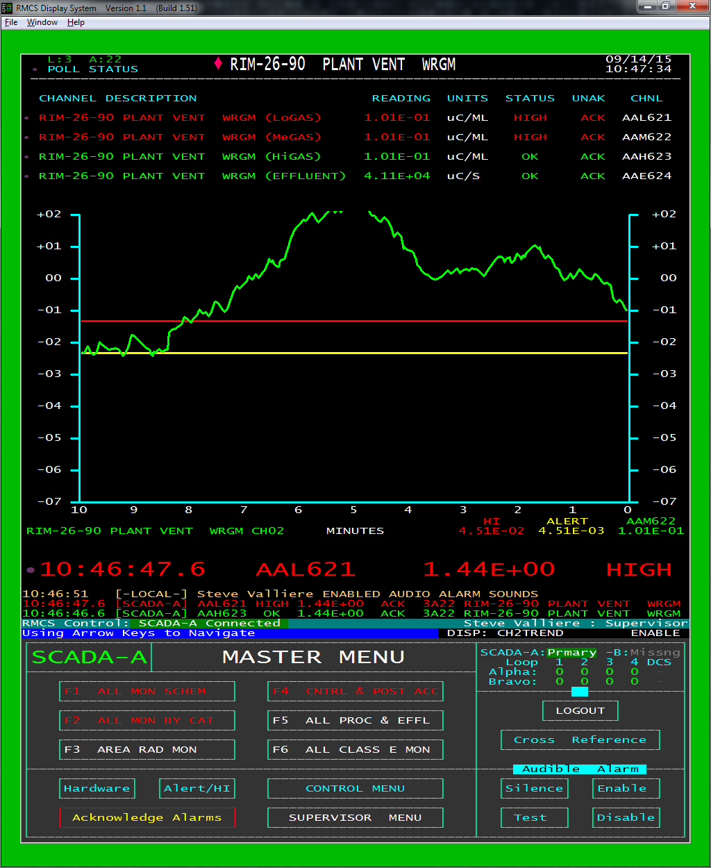
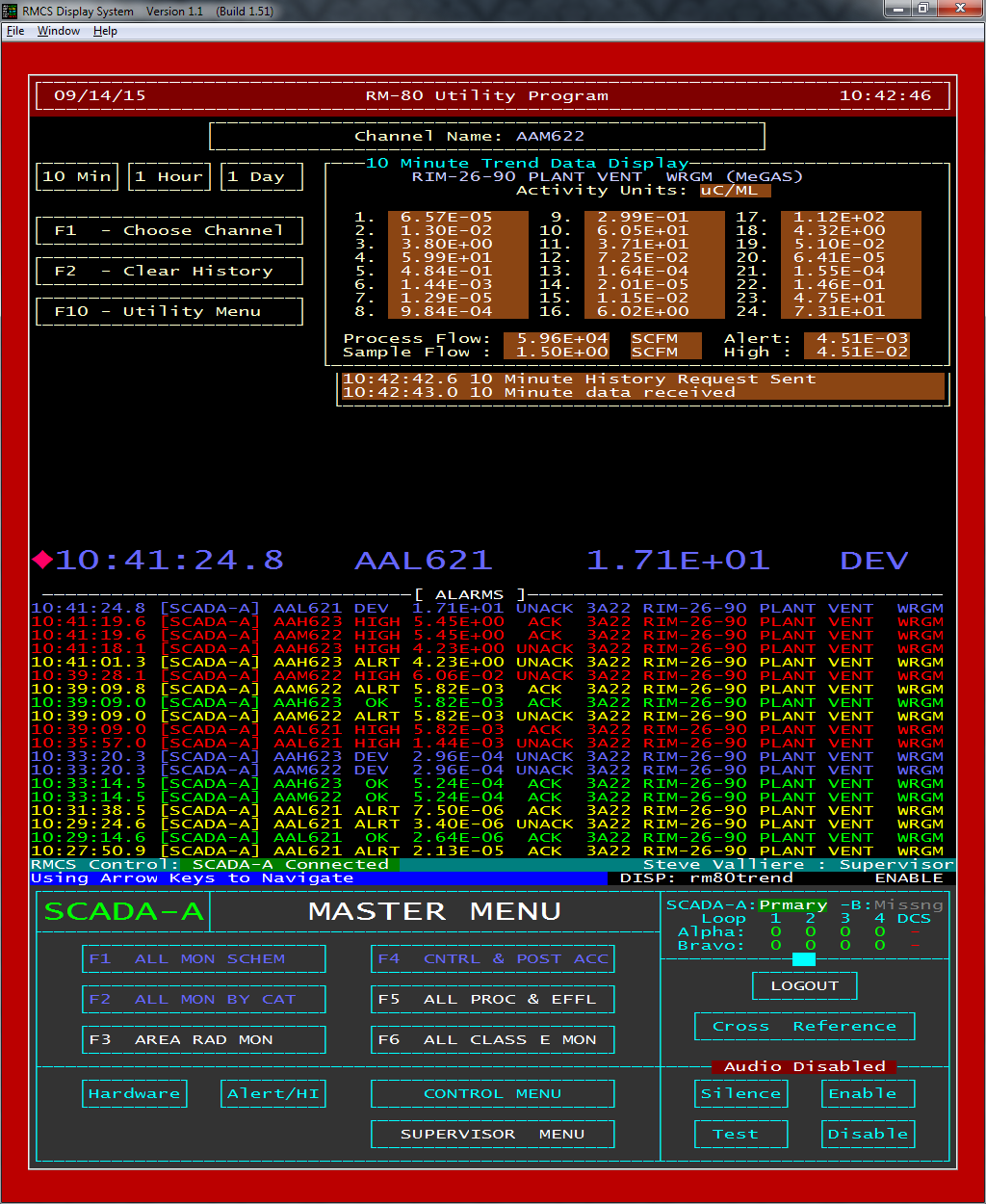
Another possibility for the MASTER screen is to show a historical trend graph of one of the channels. The trend time period may be selected from a period of 10 minutes up to a period of 24 hours. The historical data is retrieved when requested from the Plant Data Recorder (PDR) component of PICS (the software underlying RMCS).
The PICS PDR records the real time data stream being received from sensors and any other data sources to a series of binary data files, one per hour. This history is used for trending rather than the history saved by the RM-80s. This allows the history of alarm limit changes to be included on the trend.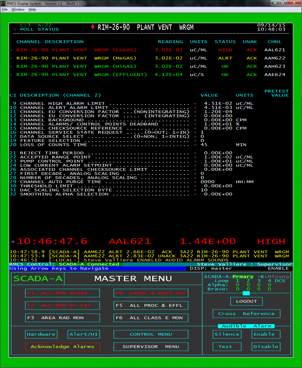
RM-80 Utilities
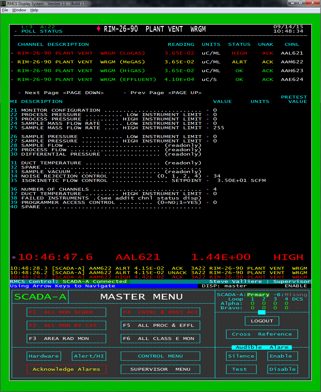
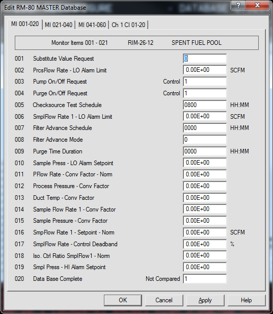
The RM-80 Database screen displays all of the "normal" monitor and channel items for an RM-80. Items outside the normal ranges are used by the RM-80 for special purposes such as history, status and internal calculations.
This screen is only accessible to supervisors and allows editing of any non-dynamic items. Writing to dynamic items (e.g. current channel reading) is prohibited by the RM-80. Note that only the CURRENT RM-80 item values are changed here!
This screen automatically compares items between the CURRENT and MASTER RM-80 databases, showing items that are different in orange. The <Ctrl+M> key-chord is used to toggle between display of the CURRENT and MASTER databases.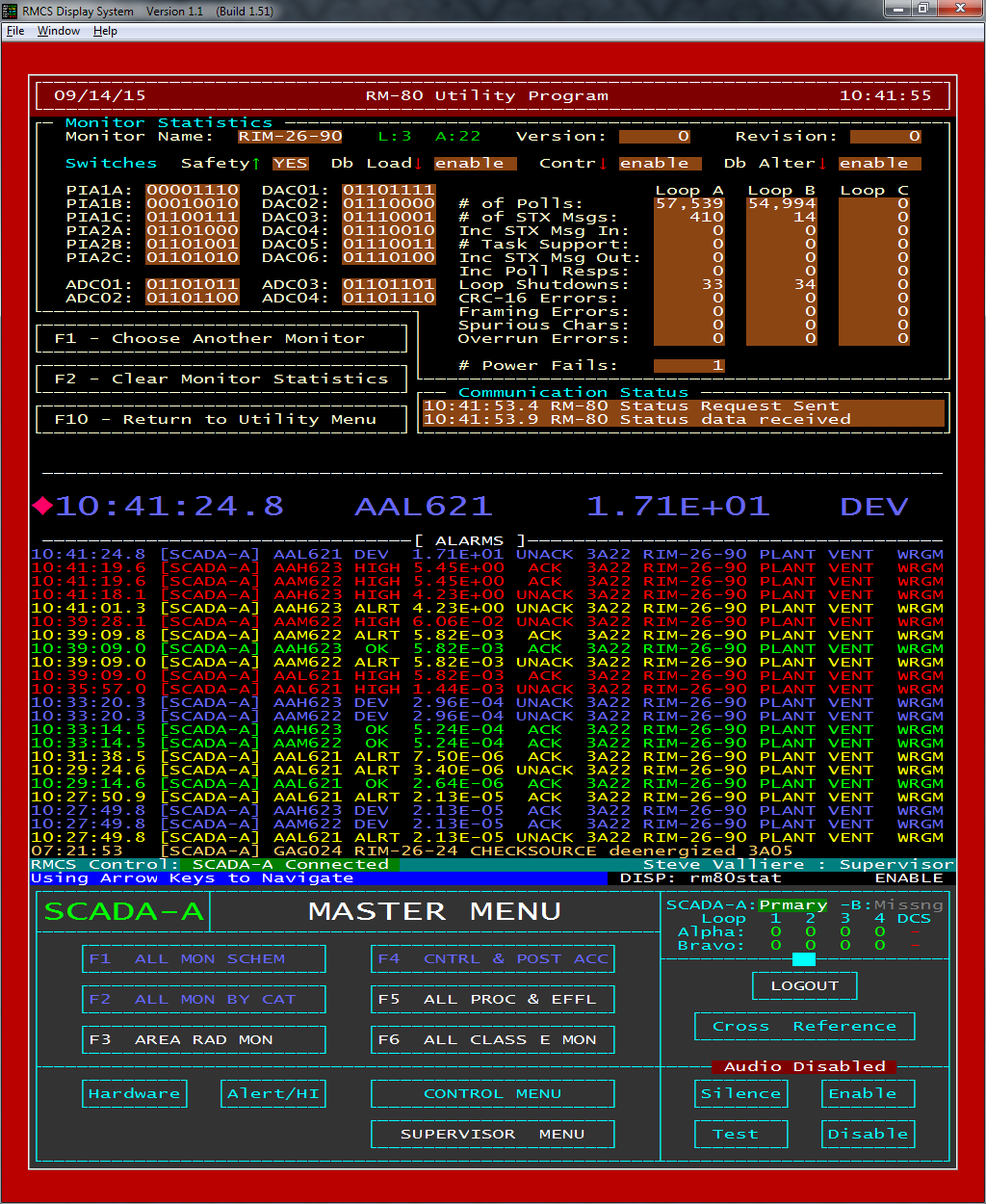
Diagnostic Screens
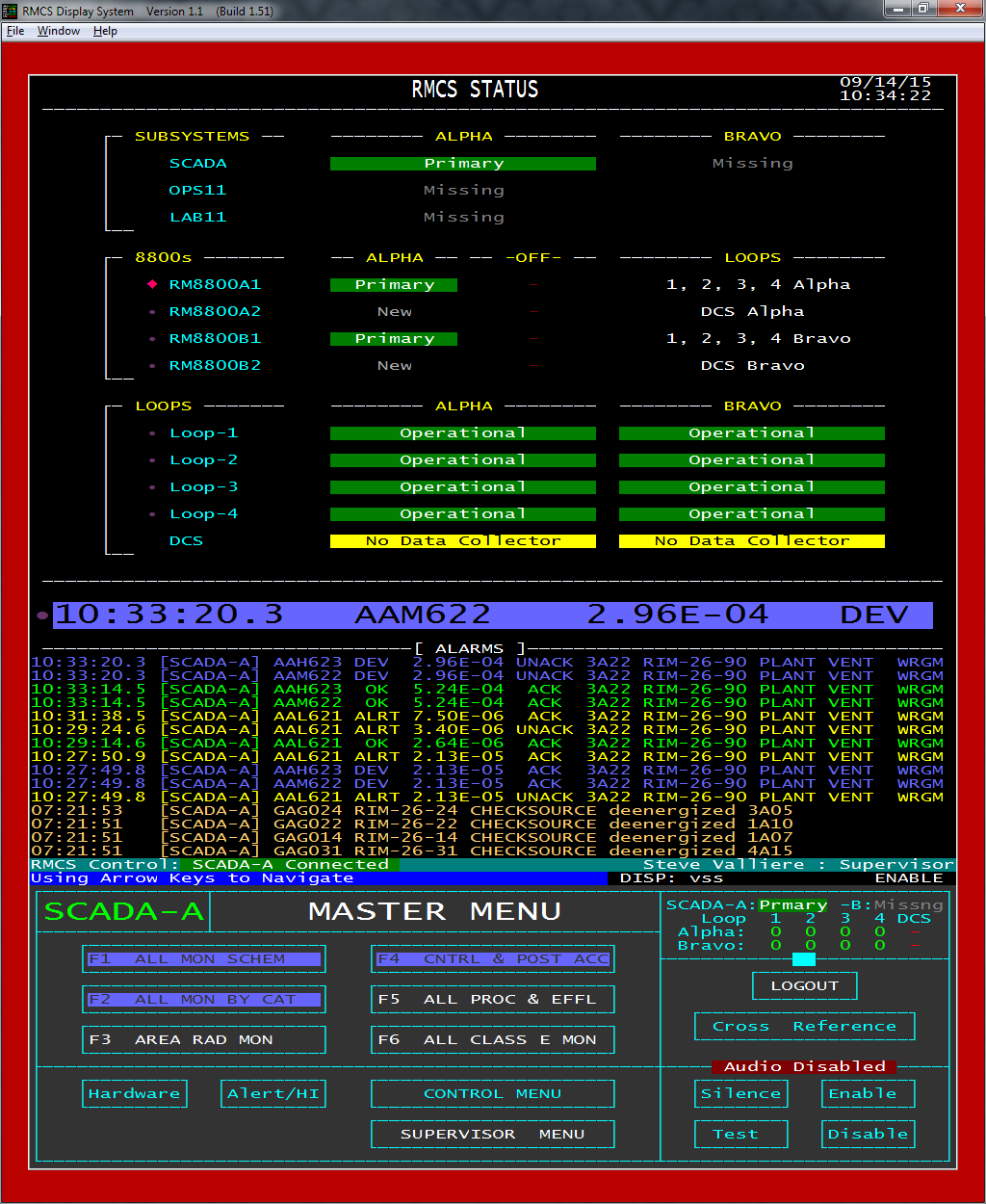
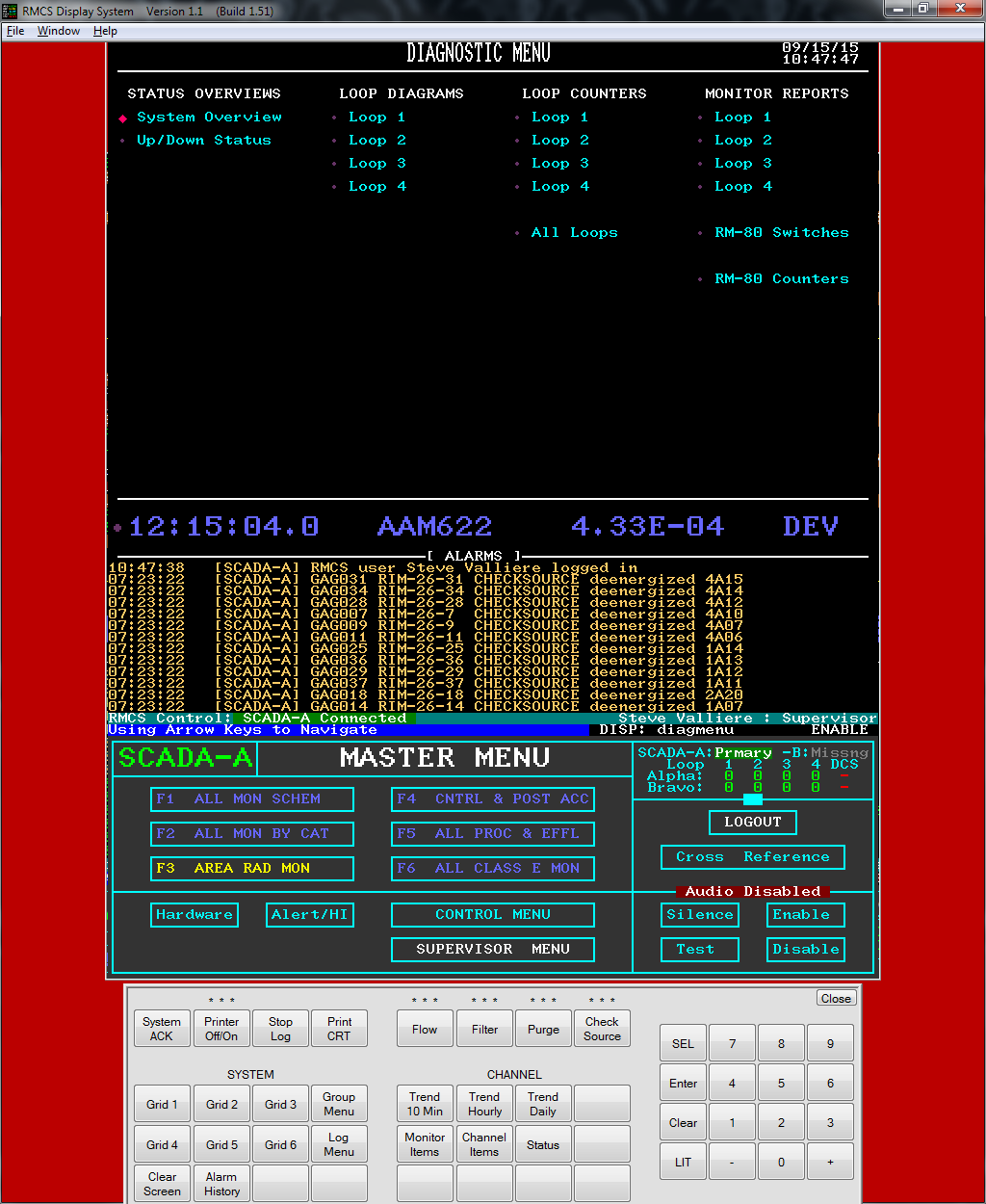
The SYSTEM OVERVIEW shows the current status of the major parts of RMCS:
- Subsystems are the Windows workstations on the private RMCS network.
- 8800s are the EVI RM8800 Loop Interface computers that provide the primary SCADA node with access to both sides of all loops.
- Loops 1-4 are the four current loops that connect sets of RM-80s into a group. The DCS "Loop" is the data connection to the plant computer system.
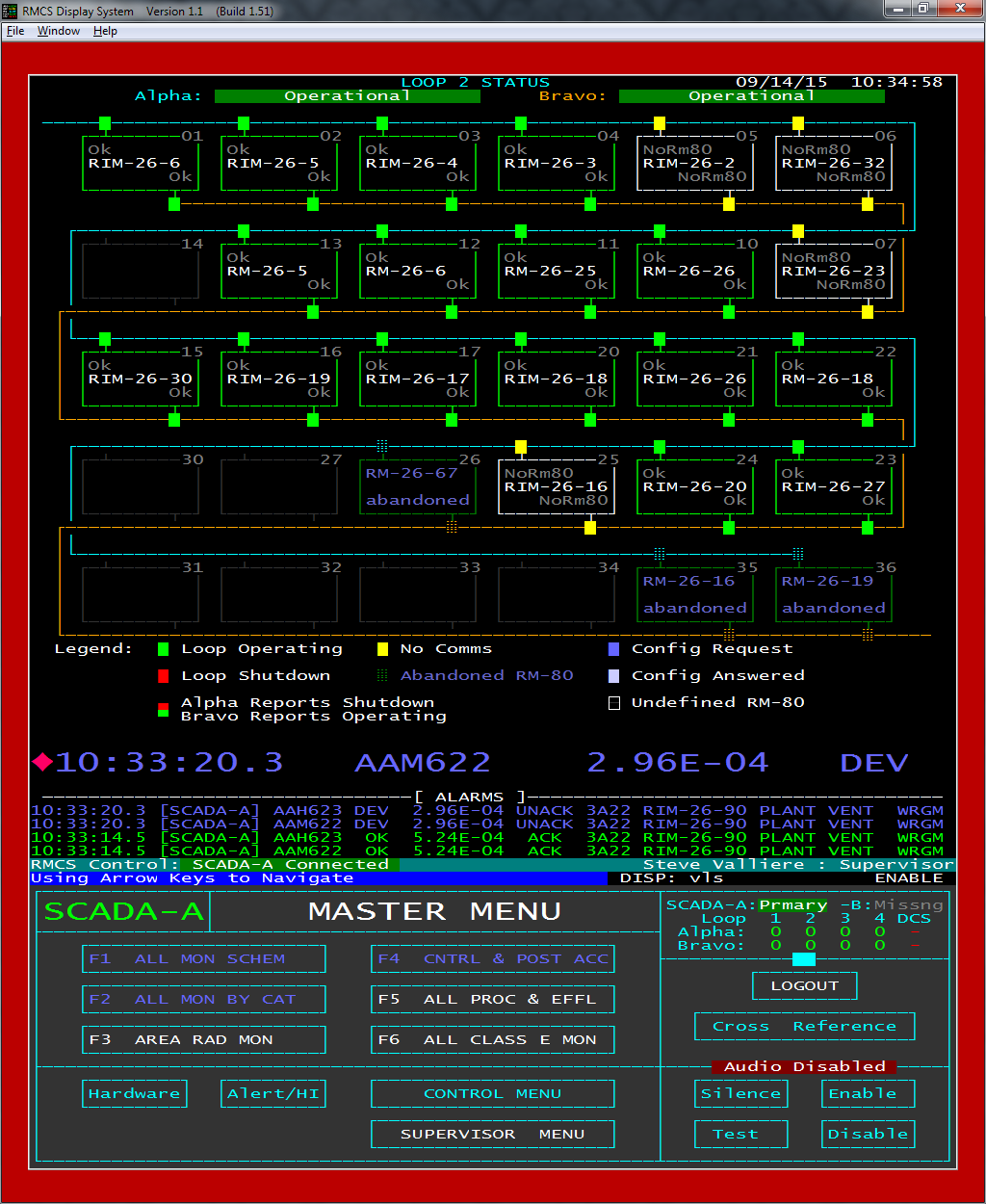
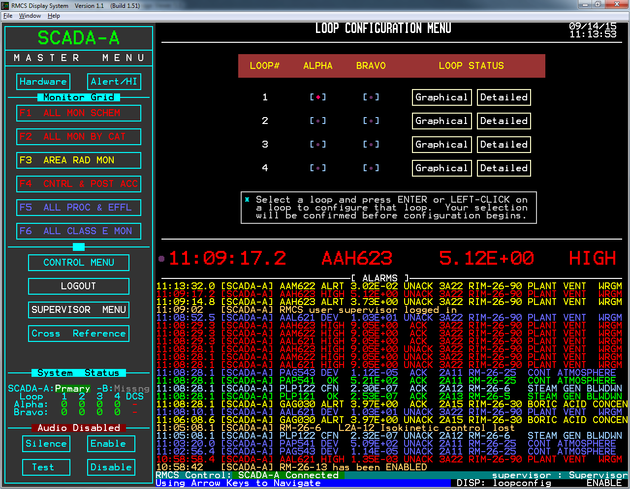
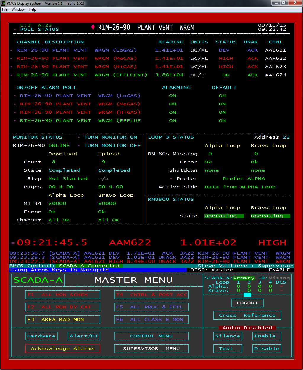
LOOP STATUS displays all of the RM-80s defined in the RMCS database for a loop and their current overall status (OK, Out of Communication, Off line, or abandoned). The points where each RM-80 connects to a loop also show the status of the RM-80's connection to that loop and, because the status may be read from both the Alpha and Bravo sides of the loop, the connect points show the status read from the Alpha side on the top half of the block and the Bravo side on the bottom half. Typically, these are the same, but when one side of loop has communications isses (for example) the conditions may appear different from the different sides of the loop.
Pressing Page Up/Page Down here will cycle through the loops.
Pressing Ctrl+Page Up or Ctrl+Page Down will switch between this screen and the loop's details status screen (see below).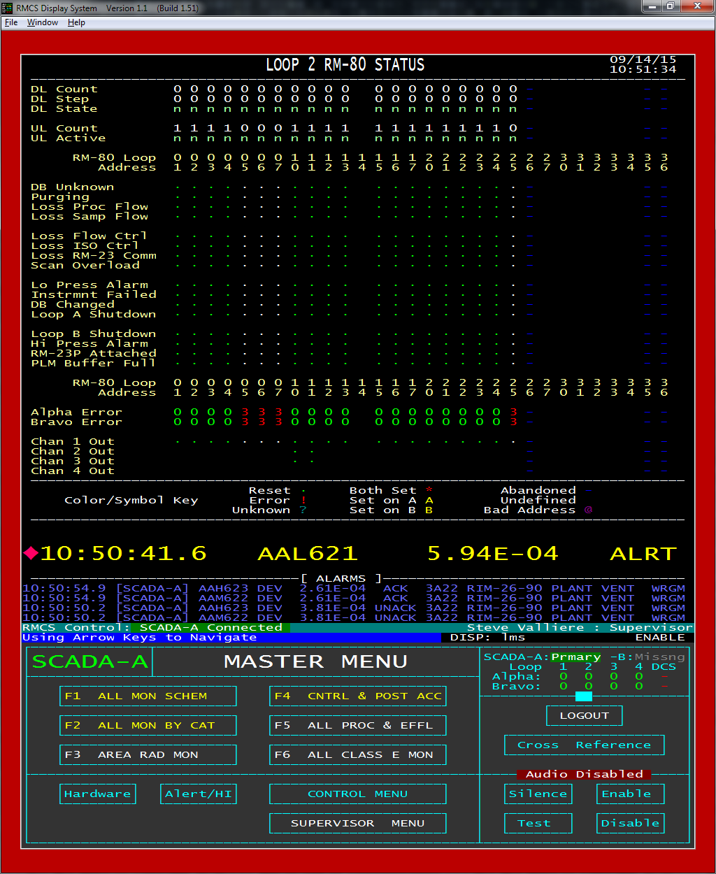
This screen composites useful information about every RM-80 on a loop. The top section shows the state of database uploads and downloads from/to the RM-80. The middle section shows the monitor status bits for every RM-80 on the loop. The bottom section shows the state of the RM-80's connection to the loop and the status of all of the RM-80's channels.
Hovering the mouse over the up/download status or the error codes on the screen will display a tool tip that translates the item into English.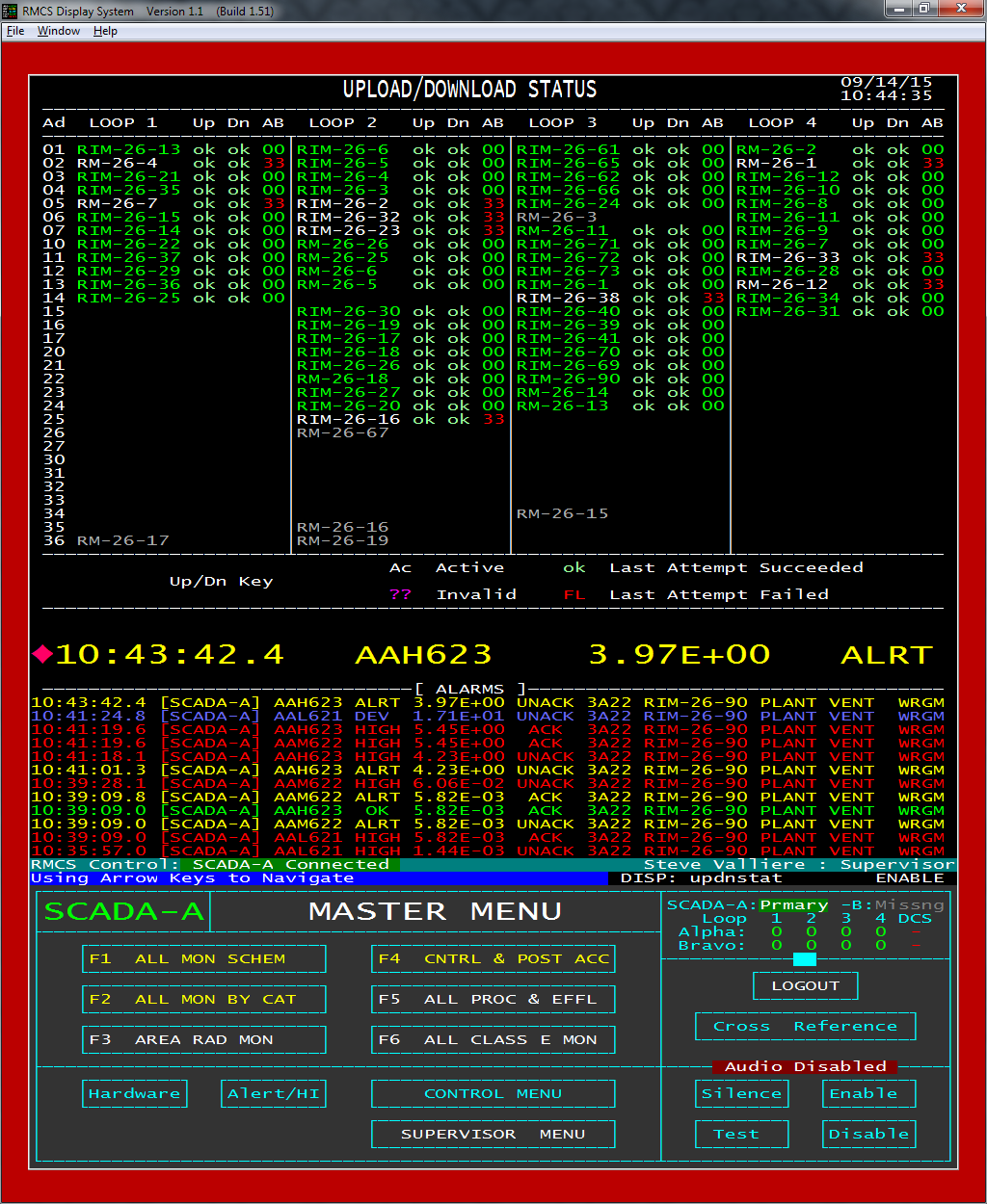
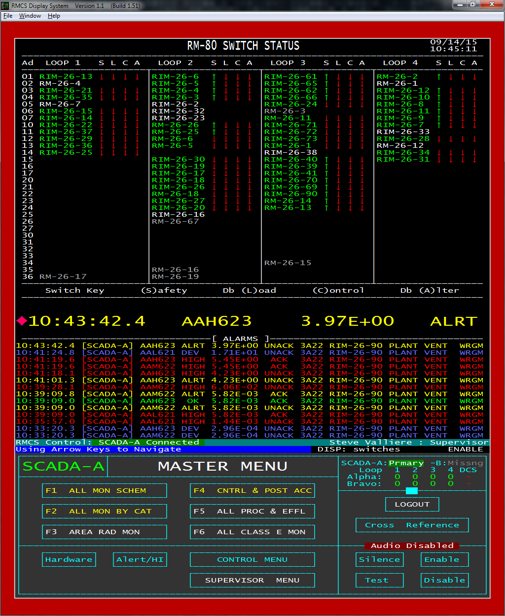
The RM-80 SWITCH STATUS screen actually reads the current switch status from ALL active RM-80s and displays the information on a single screen. The Safetly, DbLoad, Control and DbAlter switch positions are read and provided.
Because this screen is accessing every available RM-80, it will take a noticeable amount of time to complete. While the screen is being loaded, it will show which RM-80 is currently being read to indicate progress.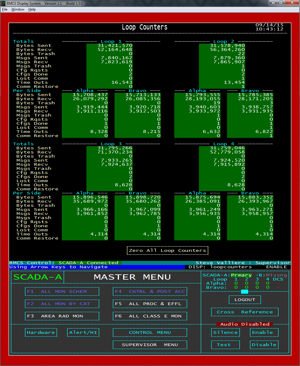
The LOOP COUNTERS screen shows an overview of the counters that the developers considered most critical/interesting. Counters are incremented each time a particular activity is performed or condition is detected.
Clicking on a loop's counters will switch to a complete list of that loop's counters.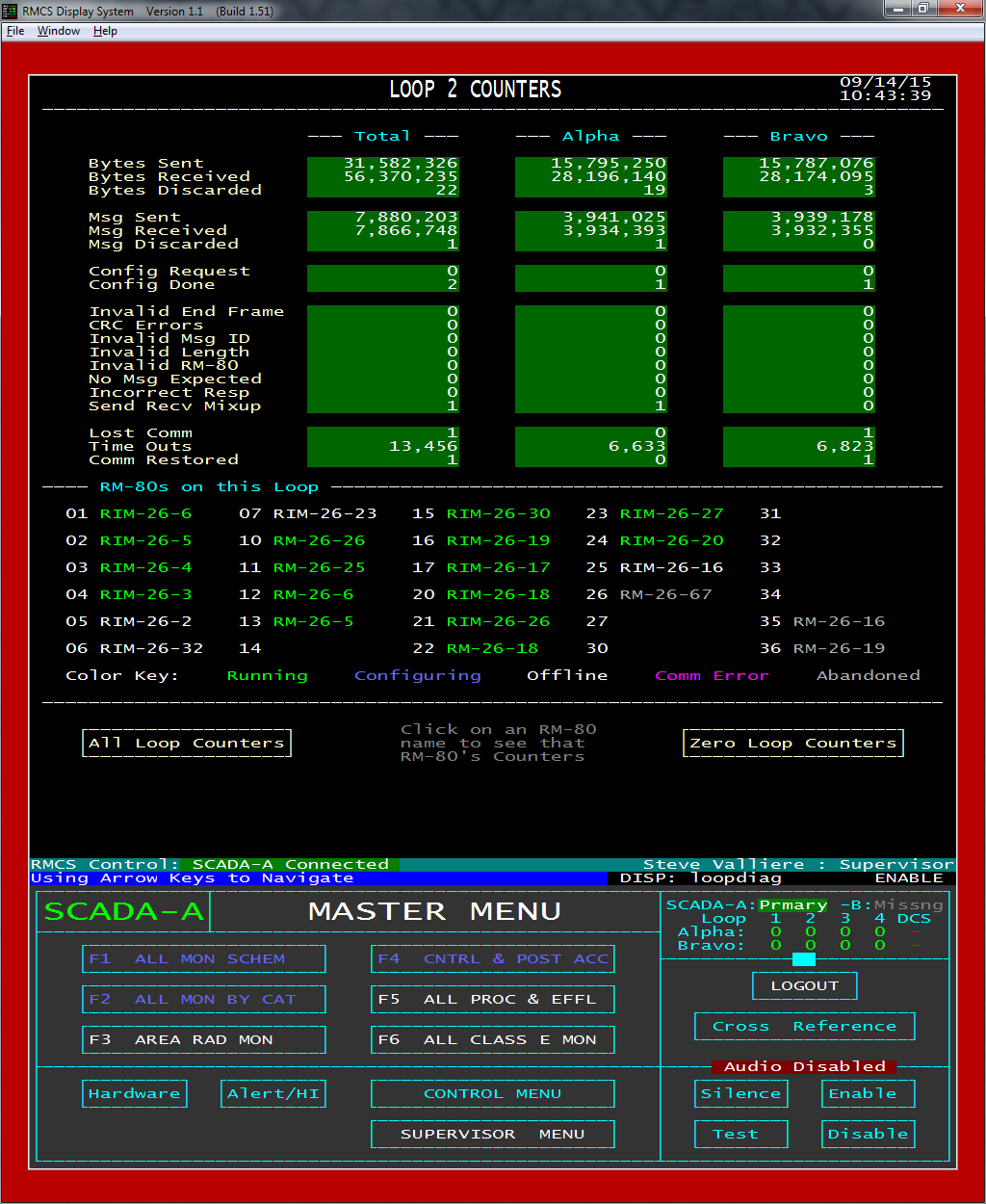
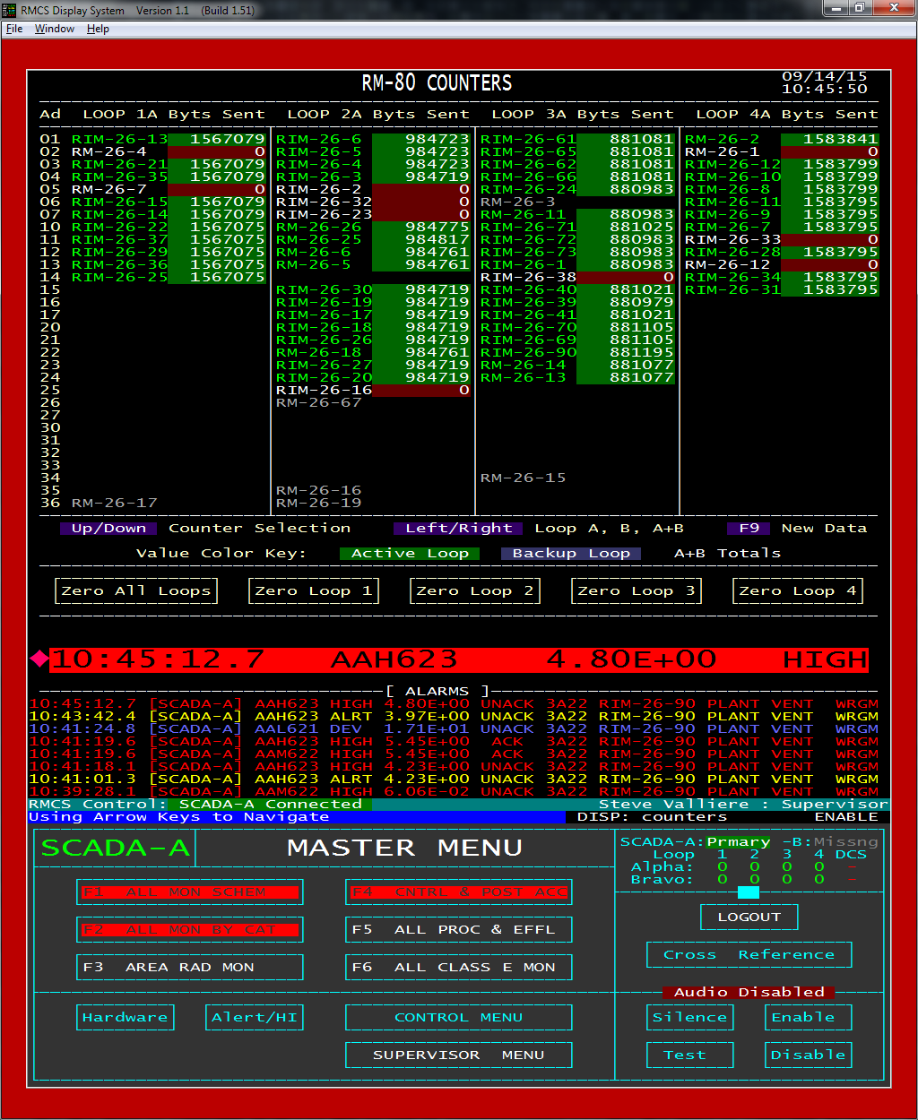
This screen shows all of the counters maintained for a loop along with a list of the RM-80s on the loop, colored by their current status.
Clicking an RM-80 will switch to a screen showing the all of RM-80's counters.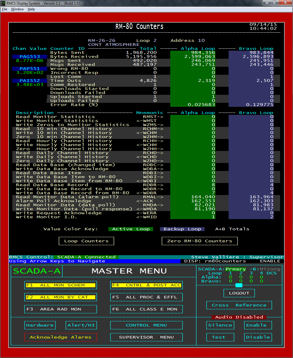
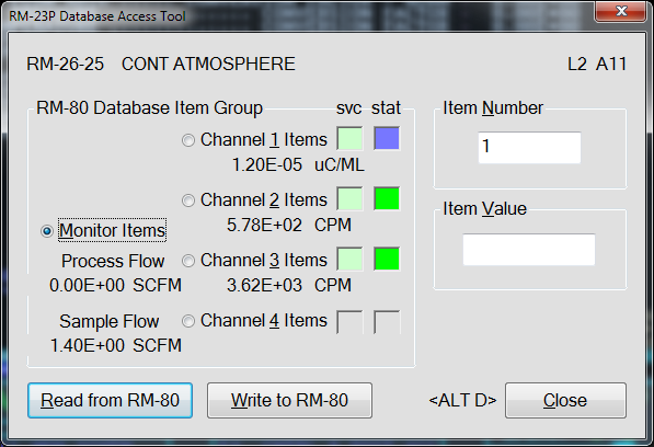
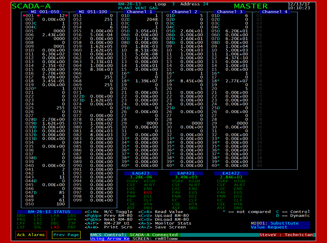
RMCS Display includes an RM-23P (like) interface that allows a supervisor-level user to read or write ANY monitor or channel item in the RM-80. Note that the RM-80s do not allow access to all addresses when reading through their Alpha or Bravo ports, however, when RMCS is operating in diagnostic mode and connected to a Charlie port, then all addresses become accessible.
This dialog also shows the current channel service status, alarm condition and value as well as the process and sample flow values (if the RM-80 supports them).RMCS User Editor
RM-80 Editor
The RM-80 Editor is a separate program from RMCS display. It requires RMCS Display to be running and a user with SUPERVISOR access to be logged in in order to operate, however. This prevents unwanted changes to the RMCS database.
The RM-80 Editor automates the process of correctly linking (or unlinking) and RM-80 with the RMCS Database, which can be a rather complex task since a single RM-80 can have between about 90 and 400 records in the database.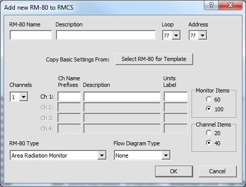
Any RM-80's MASTER database may be directly edited using this tool. This is easier (and possibly safer) than booting an RM-80 with whatever is in the MASTER database, updating the RM-80's CURRENT database as needed and then committing the changes to the MASTER database.
There is help available in the form of tool tips that may be requested using the field help button ('?') and then clicking the confusing field or clicking the HELP button to open a document that describes all of the monitor and channel items.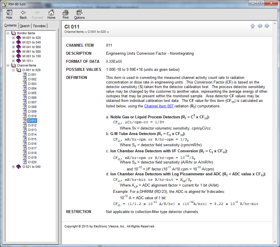
EVI's RM-80 Loop Simulator
EVI’s RM-80 Loop Simulator is not intended to be a high fidelity simulation of RM-80s. Its main purposes are to simulate the communication protocol, produce channel values, allow changes to each of the monitor and channel status values, and simulate the control functions. With this tool, most of RMCS can be tested.
FEATURE LIST:
- The current simulation conditions can be saved in a file. This allows a simulation to be restarted where it left off. The saves can be automatic and on demand.
- Both the Alpha and Bravo sides of up to four loop are supported, totaling up to eight serial port connections.
- The simulator can also directly talk to RMCS without use of serial connections.
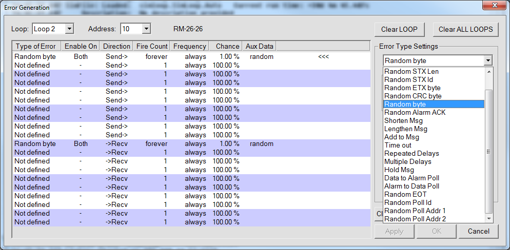
- Twelve different types of communication errors may be generated. Each RM-80 may have several error types defined for it.
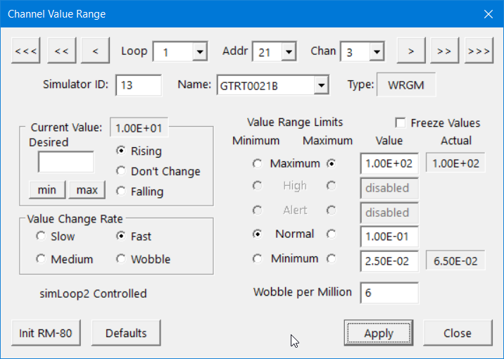
- Channel values are generated in a random walk fashion. The limits of the value may be set to cover a wide range of values or limited to normal operation and alarm levels.
- Changing monitor and channel status flags allows RMCS to react to concepts not generated in the simulation, including invalid RM-80 behaviors.
- Physical RM-80 switches are emulated within the simulator, including power and CPU reset.
- Control functions cause appropriate changes in the status values of the monitor and its channels.
- Logging may be turned on to show the serial communication information, user changes to the simulation and internally generated communication errors.
- There is a command mode that allows most of the GUI interface to be generated in a command line mode. It accepts scripts which allows various canned scenarios to be easily repeated. Various reports can be generated such as of RM-80 values and database, and loop
Using all the features to simulate all of the errors and problems could make a true plant operator run for the hills!
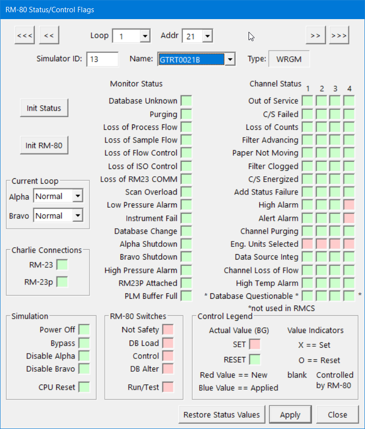
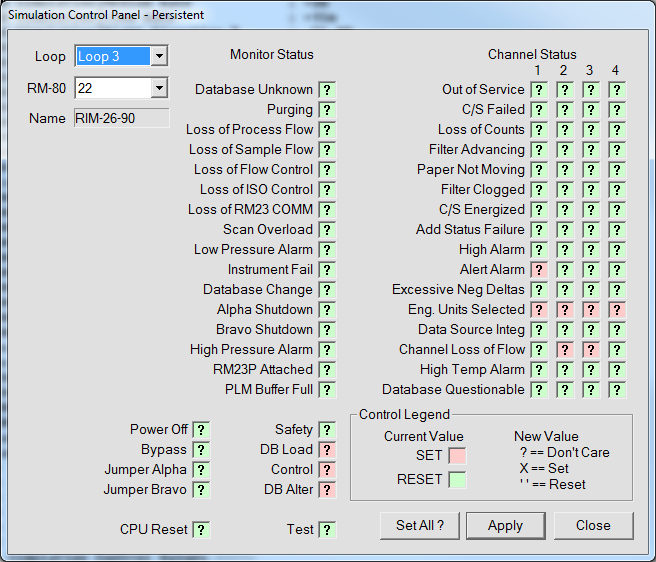
The Monitor and Channel status bits may be controlled, along with a few other toggles such as power, bypass and the RM-80 switch settings. The bits may be set in two ways:
- Immediate
- Bit settings applied BEFORE the next run through the RM-80 value generator. These may or may not end up propagating to RMCS.
- Persistent
- Bit settings applied AFTER the RM-80 value generator so that they are ALWAYS sent to RMCS.
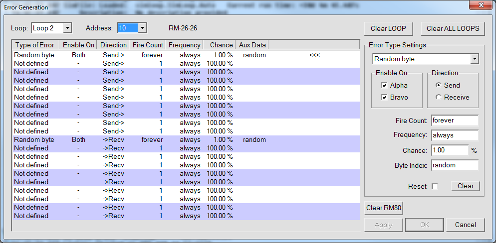
Since EVI's loop simulator was developed to test the RMCS software, the capability to mimic serial error conditions we have seen or imagined. This has allowed for more robust serial error handling by RMCS.
Error generation may occur randomly and/or periodically, limited to a specific number of firings, be specified for data received or sent and which loop side it applies to. Error generation events may be logged, making it easier to ensure that the error was detected and handled by RMCS when testing.
1555 Magnolia Street NE ✦ Palm Bay, FL 32905 ✦ (321) 632-7530