RM-80 Loop Simulator
Apr 19, 2024
Disclaimer
EVI's RM-80 Loop Simulator, Mark 2 (simLoop2) is first
and foremost a simulator of RM-80 LOOP COMMUNICATION.
simLoop2 is NOT intended to fully simulate the internals of
RM-80 processing!
Overview
EVI's RM-80 Loop Simulator (simLoop2) application has a very basic appearance with a standard window title, frame & menu surrounding an area used for logging text messages about program activity.
The primary purpose of simLoop2 is to simulate RM-80 data loop communication and many of the communication issues that have been reported on the loops. The secondary purpose is to support some very minimal emulation of RM-80 functions by setting/resetting the appropriate monitor and channel status flags in response to control inputs and the simulated channel readings. Channel readings are generated by performing a random walk of each channel reading up and down within a specified range.
simLoop2 can use either serial ports to communicate with RMCS (through actual RM8800s) or simulate the RM8800s and communicate with RMCS directly over a network. The RM8800 is an EVI product that collects a group of serial ports and makes them available to RMCS over Ethernet, providing both the primary and backup SCADA machines with access to all RM-80 loops, both on the Alpha and Bravo sides.
simLoop2 supports EVI’s RM-23S devices over Ethernet. The RM-23S device is an EVI product that looks exactly like an RM-23A, but the RM-23S is designed to communicate with simLoop2 using a network instead of with an RM-80 using current loop.
Local simLoop2 Activities
The simLoop2 user interface allows control over almost all aspects of the active simulation session. simLoop2 configuration is stored in a set INI files that are processed when simLoop2 is started.
Working with Channel Values
The Channel Value Range dialog allows some control over the simulated values being generated by simLoop. Before a new value may be entered, one of the radio buttons must be clicked. When changing the min/max radio button selections, be aware that the dialog will not allow the Minimum to be above the Maximum. Until something is clicked to lock the text input fields, the Current Value field will update as the value changes.
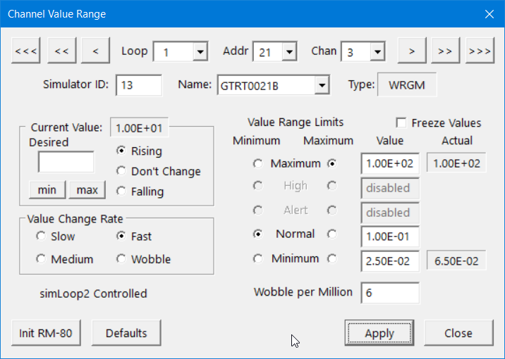
The Init RM-80 button appears in multiple dialogs and will restore the entire RM-80 to the initial state for all channels, values, ranges, status bits, etc.
The Defaults button restores all of the channel’s value range settings to their initial defaults without affecting any other part of the RM-80 simulation.
The RM-80 Name and Type come from simLoop2’s configuration file. While this file typically matches the simulated site, some tests may require the addition additional RM-80s to simulated unexpected communication loop traffic. Individual channel names are not included in the loop simulator configuration.
Status/Control Bits
The Status/Control Bits dialog allows the user to manually set any of the monitor or channel status bits that are being reported to RMCS. When the value shows a question mark, the bit’s value is controlled by simLoop2. Otherwise, the value will be whatever was manually set. The background color indicates the most recently reported value.
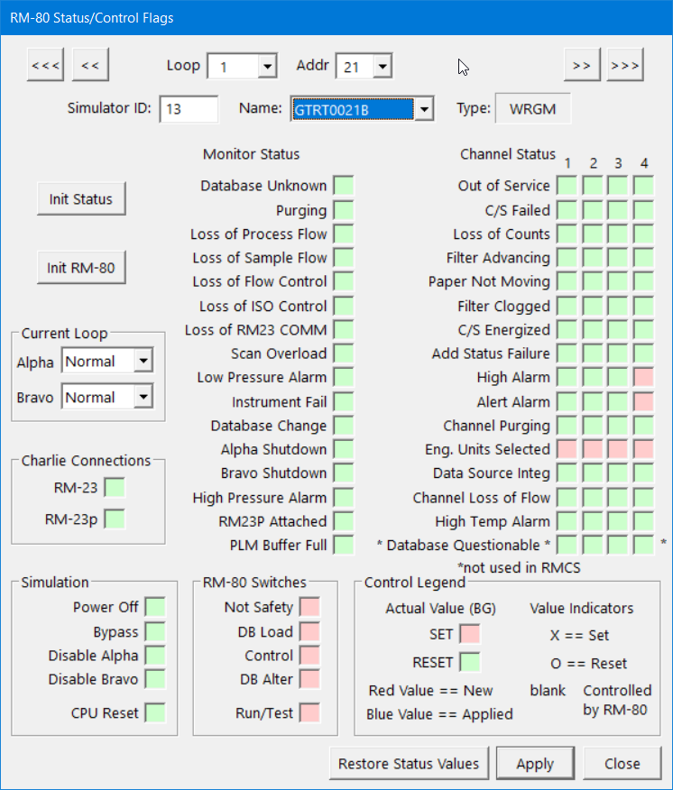
Click three times to cycle through the three possible settings for a bit. If you are too fast, Windows may interpret some clicks as Double-Click events, which are ignored.
The bits in the Power Off and Safety groups are simulation controls and RM-80 switches, respectively. The RM-80 simulation respects the settings of the DB Load, Control, and DB Alter switches by refusing to perform the associated functions when the switch indicates the function is inhibited.
The Current Loop options can instruction simLoop2 to introduce either line noise (‘garbage’) or to terminate the loop at this RM-80 on the specified loop side.
Error Generation
The Error Generation dialog is used to configure any of the various types of loop communication errors that simLoop2 is capable of simulating.
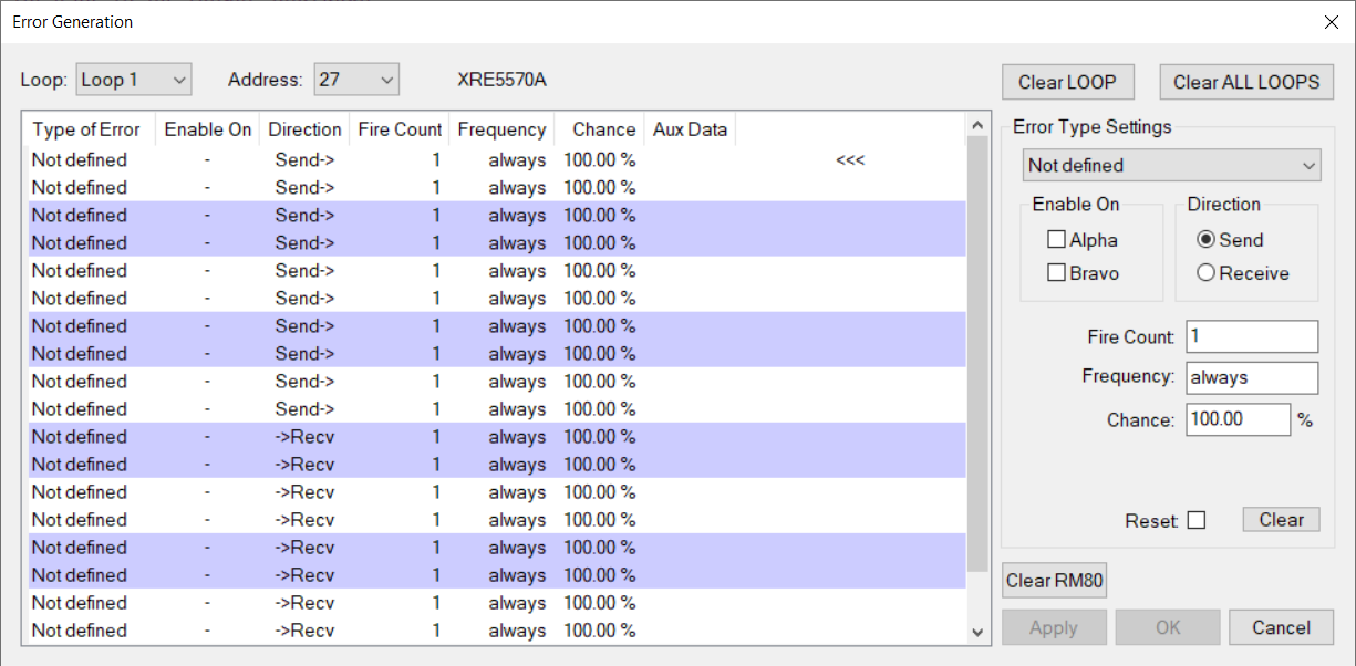
Errors are configured on a per RM-80 basis, though the dialog also includes buttons that allow all defined errors for an RM-80, Loop, or All Loops to be cleared quickly and easily.
Errors may be enabled for either loop side or both.
Errors configured for the Send Direction will affect messages being sent from the RM-80 to RMCS. These are the most commonly used errors. The Receive direction affects the messages from RMCS to the RM-80 and generally result in the RM-80 simply ignoring the message.
Fire count sets a limit on the number of times that the error should be triggered. Set this value to zero indicate that there is no limit (the text will change to ‘forever’ when the settings are applied.)
Frequency sets how often the error might occur. A value of zero means that every time it is possible for the error to occur, it might occur. Any other value (N) means that the error might be triggered every Nth time that it is possible for the error to be generated.
Chance provides a way to have intermittent errors by introducing
an optional random element into the error generation. A value of 100% means the
error will occur every time that the Fire Count and
Frequency allow. Any lower percentage sets the change that the
error might fire each time it is allowed.
There are 20 error generation slots available for each RM-80 in
the system. This allows a single RM-80 to be configured to generate more than
one type of error.
Monitor Items
This dialog displays the Monitor Items for the selected RM-80, one page at a time. (The RM-80 groups items into pages of 20 items for bulk read/write requests.) Dynamic items cannot be changed using this dialog and are marked as Read Only (normally that will mean they have a gray background, but local Windows settings may change that.) Dynamic values are updated periodically while the dialog is open.
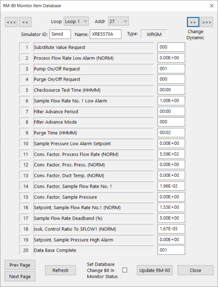
New values should be entered using the same format used for the original value being altered. The Refresh button will reload ALL 20 of the values on the current page. When changes are made, you have the option to Set Database Change Bit In Monitor Status so that RMCS can detect the change and upload the changed value(s). The Update RM-80 button applies the changes (and change bit) to the RM-80.
Channel Items
This dialog displays the Monitor Items for the selected RM-80, one page at a time. (The RM-80 groups items into pages of 20 items for bulk read/write requests.) Dynamic items cannot be changed using this dialog and are marked as Read Only (normally that will mean they have a gray background, but local Windows settings may change that.) Dynamic values are updated periodically while the dialog is open.
Channel Item 18 is a special case because although the Raw Counts Totalizer is updated by the RM-80, you may check the box next to it in order to enter a value to reset the Totalizer.
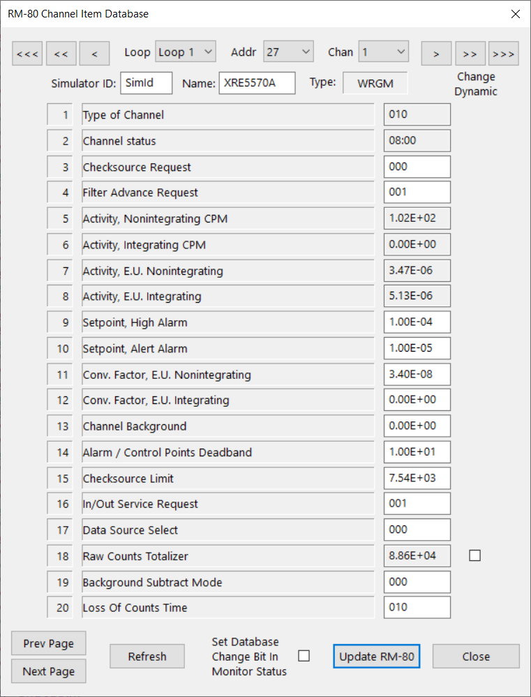
New values should be entered using the same format used for the original value being altered. The Refresh button will reload ALL 20 of the values on the current page. When changes are made, you have the option to Set Database Change Bit In Monitor Status so that RMCS can detect the change and upload the changed value(s). The Update RM-80 button applies the changes (and change bit) to the RM-80.
PIA Bits
This dialog allows display and control of the PIA Input/Output values as well as some simulation control settings.
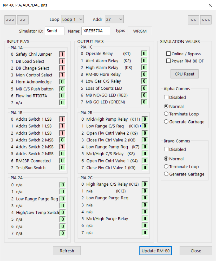
Each PIA item contains 8 single bit values. When the dialog is loaded, the text (1/0) and the background color (red/green) are updated periodically to reflect the current values. When you click a PIA bit to change the value, the TEXT for all 8 bits in the PIA that was clicked will stop updating, while the background color will continue to show the current bit values.
The Online/Bypass and Power RM-80 OFF checkboxes allow the simulated RM-80 to either be bypassed on the (simulated) loop or to be powered off.
The CPU Reset button will cause the simulated RM-80 to behave as it its CPU had actually been reset. This means that the RM-80 will report “Database Unknown” and attempt to trigger a download from RMCS.
Finally, the RM-80’s Alpha/Bravo Communications may be Disabled or changed to be Normal or cause a problem on the loop by either Terminating the Loop after the RM-80 or Generating Garbage (noise) on the line.
Plant Simulator Interface
Some sites may be interested in using simLoop2 to allow the plant simulator to provide data and control inputs (e.g. power, etc.) for the RM-80s so that RMCS may receive and process the data as if it had come from the real plant loops. We are currently testing new code that was added for this purpose, however, the actual interface to each plant simulator computer system has been different for every customer (so far). The uniqueness of each plant simulator requires the creation of a custom communication module for use between simLoop and the plant simulator and EVI will do this for you, once we have the necessary protocol definitions.
RM-23S Support
simLoop2 also supports EVI's RM-23S devices (connected over Ethernet) to replace existing RM-23 units that may be valuable as spares for the control room.
simLoop2 Command Line
simLoop2 also includes an internal command line that may be used for advance usage. The command line also supports executing script files that contain a series of commands to be executed. Scripts can be created to configure simLoop2 for specific conditions in an easily repeatable way.
simLoop2 Scripting Capability
simLoop2 supports scripting using a BASIC language syntax that allows customised control of almost all of simLoop2's behaviors. simLoop2 includes an interactive debugging tool for scripts as well:
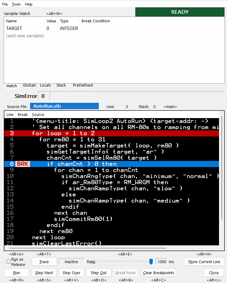
Scripts may be used to generate special test cases that need to be repeated exactly each time they are performed. You may also create an AutoRun script that simLoop2 will run automatically every time the program it started in order to configure the simulator exactly as you prefer.
Note that BASIC Scripting is an optional feature that incurs an additional cost.