Master Menu
Apr 19, 2024
 This
page will describe the RMCS Display MASTER MENU from top to bottom.
This
page will describe the RMCS Display MASTER MENU from top to bottom.
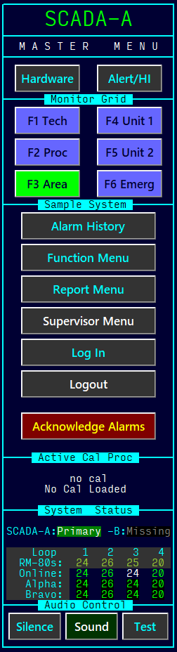
The top item, SCADA-A on the menu identifies the particular RMCS Node (a node is an individual RMCS computer) where RMCS Display is running. The color indicates the node's status:
- Green – The node is Primary (this is the controlling node in a primary/backup pair)
- Orange – The node is Backup
- Cyan – The node is a Peer (this node may or may not be part of a pair, but each node operates individually)
The MASTER MENU line identifies the menu panel and also functions as a clickable area that will display a screen containing all of the items that may also be found on the RMCS Display program's menu bar. This menu can be useful when running in full screen mode, with the title and menu bars hidden.
The Hardware and Alert/HI buttons activate quick alarm summary screens that show the active hardware or limit alarms, respectively. These screens show active alarms ONLY — they do not show history! These may be removed to reclaim this space for another use, if desired.
The block of Monitor Grid buttons serves two purposes:
- Clicking a grid button will activate the associated grid screen.
- The button color matches the WORST alarm that currently exists on the grid screen. A flashing button indicates a grid with an unacknowledged alarm.
- A setting is available to allow clicking on a flashing grid button to acknowledge the alarms on that grid when the grid is already visible.
The Sample System marker is an optional label used in the development/test systems to distinguish these screen shots from those captured in a live system. In a live system, this will typically be a site identifier as configured by the site Administrator. If no identifier is desired, the setting may be left blank and a small block will be displayed as a placeholder for the ID.
The column of buttons in this sample show some of the most common options to include on the master menu. Any or all of these may be altered to meet customer needs. Some of these buttons only appear when a user with the necessary security access level is logged in to RMCS Display.
The Acknowledge Alarms button will be visible any time there is at least one channel reading visible on the screen that might show an alarm that requires acknowledgement (the alarm bar alone(described here) does not trigger the Ack Alarms button to be visible)
The Active Cal Proc block will only be present when the Calibration Tool is included in the software license AND there is at least one calibration procedure defined in the calibration procedure database file. When this block is present, it acts as a clickable button to choose, switch to or control a calibration procedure.
The System Status block shows the status of the two SCADA nodes (these are the nodes that poll the RM-80 loops for data) as well as an overview of the loops. In the loop overview, there is a column of numbers for each loop. Here's what the numbers mean:
- RM-80s – The number of RM-80s there are defined as belonging to the loop in the RMCS Database
- Online – The number of RM-80s that are marked online for the loop in the RMCS Database
- Alpha – The number of RM-80s currently communicating on the alpha side of the loop
- Bravo – The number of RM-80s currently communicating on the bravo side of the loop
For Online, Alpha and Bravo, a GREEN value indicates the currently expected value.
For Online, a WHITE value indicates that at least one RM-80 on the loop is marked OFFLINE.
For Alpha/Bravo, a RED value indicates that at least one RM-80 is MISSING and a BLUE value is used when the loop is performing a Loop Configuration.
Finally, the Audio Controls buttons can affect the alarm sounds without acknowledging any alarms:
- Silence – will stop the currently playing sound without acknowledging the alarm that triggered the sound
- Sound – will confirm the intent to mute all alarm sounds. When sounds are muted, the button text will change to Mute and the background color to red.
- Test – will play (on a loop) a test sound to verify the speakers are working and the volume is set correctly. By default, this sound is quite different from the actual alarm sound to ensure operators do not confuse it with an alarm.